- 您现在的位置:买卖IC网 > Sheet目录222 > EB81-S0K1860X (Vishay Dale)CONN EDGEBOARD DUAL 36POS 5A
EB8
Vishay Dale
Edgeboard Connectors, Dual Readout
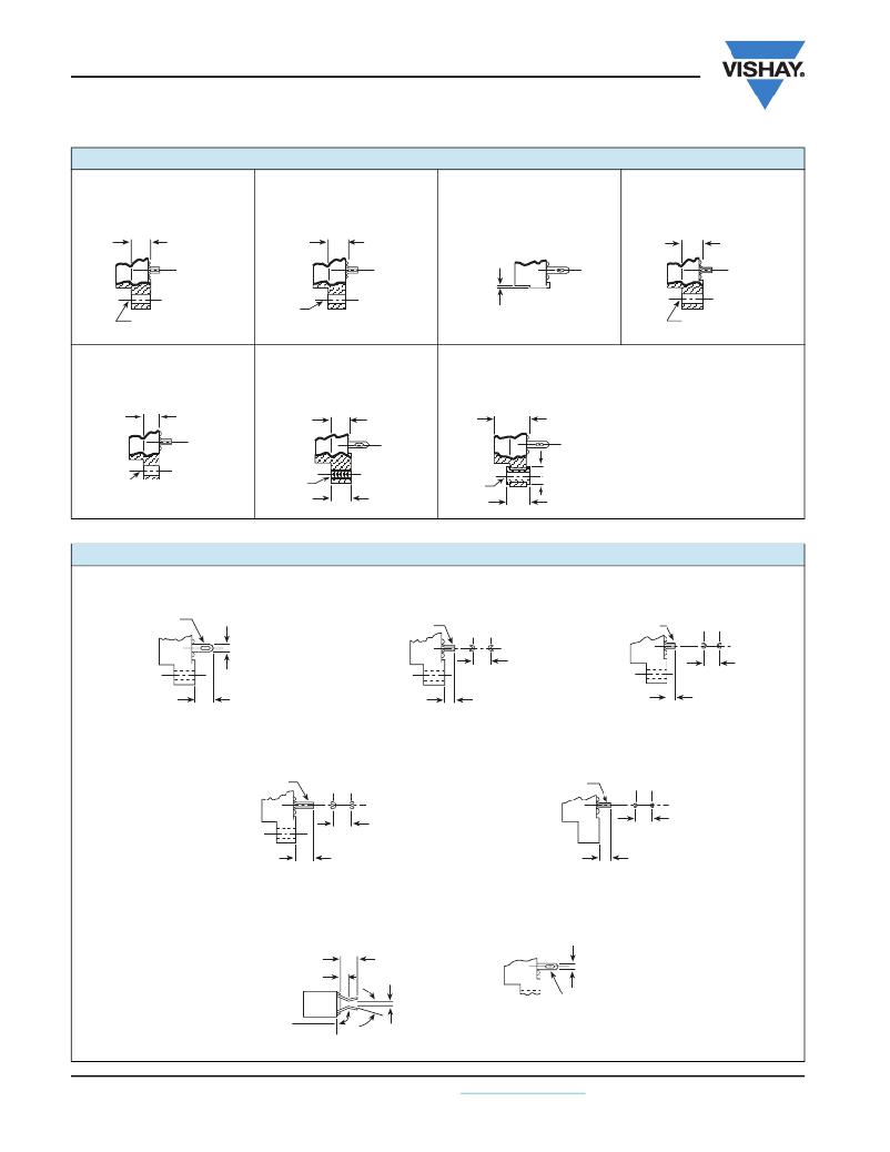
MOUNTING VARIATIONS in inches (millimeters)
Type “V”
Clearance Hole
Type “VI”
Clearance Hole
Type “W”
No Mountin g Flan g e
Type “X”
Clearance Hole
No Mountin g Pad
0.250
(6.35)
Ref.
0.142
(3.61)
0.220 (5.59)
Ref.
0.250
(6.35)
Ref.
0.142 (3.61) Dia.
Dia.
0.010 (0.254)
0.000 (0.000)
0.12 8 (3.25) Dia.
Type “XI”
Clearance Hole
No Mountin g Pad
0.220 (5.59)
Ref.
Type “Y”
Threaded Insert
0.250 (6.35)
Ref.
Type “Z”
Floatin g Bushin g Radial Float 0.047 (1.19)
0.250 (6.35)
Ref.
Note: O v erall b ody length
0.12 8
(3.25)
Dia.
4-40
UNC-2B
0.250 (6.35)
Ref.
0.116
(2.95)
Dia.
0.250 (6.35)
Dia.
0.270 (6. 8 6)
increased b y 0.060 (1.52)
TERMINAL VARIATIONS in inches (millimeters)
Type “A”
Type “C”
Type “D”
To fit 3,
Pierced
Solder Dip
#22 AWG
Wires
0.0 8 6
(2.1 8 )
0.200 ± 0.015
To fit 0.051 (1.30)
Min. Throu g h Hole
0.200 ± 0.015
(5.0 8 ± 0.3 8 1)
To fit 0.051 (1.30)
Min. Throu g h Hole
0.200 ± 0.015
(5.0 8 ± 0.3 8 1)
(5.0 8 ± 0.3 8 1)
Type “K”
Solder Dip
To fit 0.051 (1.30)
Min. Throu g h Hole
0.200 ± 0.015
(5.0 8 ± 0.3 8 1)
0.200 ± 0.015
(5.0 8 ± 0.3 8 1)
0.125 ± 0.015
(3.1 8 ± 0.3 8 1)
0.104 ± 0.015
(2.64 ± 0.3 8 1)
Type “L”
Solder Dip
To fit 0.036 (0.914)
Min. Throu g h Hole
0.200 ± 0.015
(5.0 8 ± 0.3 8 1)
0.156 ± 0.015
(3.96 ± 0.3 8 1)
Type “E”
Card Extender
0.200 ± 0.015
(5.0 8 ± 0.3 8 1)
0.0 8 6
0.100
(2.54)
(2.1 8 )
120°
Typ.
15°
0.050
(1.27)
Uses
Type “A”
Contact
Typ.
www.vishay.com
16
For technical questions, contact: connectors@vishay.com
Document Number: 36005
Revision: 16-Feb-09
发布紧急采购,3分钟左右您将得到回复。
相关PDF资料
EBA44DRAS
CONN EDGECARD .125 R/A 88POS
EBC49DTBS-S605
CONN EDGECARD 98POS R/A .100
EBM28MMRD
CARD MALE EXTENDER .156 56POS AU
EBM36MMJN
CARDEDGE MALE 72POS .156 R/A AU
EBM36MMWN
CARDEDGE MALE 72POS .156 T/H AU
EBT156-22D2Y
CONN EDGEBOARD SINGLE 22POS 5A
ECC09DJXN
CONN EDGECARD 18PS .100 PRESSFIT
ECJ26DSCI
CONN EDGECARD 52POS .150 SQ WW
相关代理商/技术参数
EB81-S0K2240X
功能描述:标准卡缘连接器 EB81-K22SGFXT02 RoHS:否 制造商:3M Electronic Solutions Division 系列:SPD08 产品类型:Contacts 位置/触点数量:60 安装角:Straight 电路板厚度: 安装风格:SMD/SMT 节距:8 mm 外壳材料:Liquid Crystal Polymer (LCP) 触点材料:Copper Alloy 触点电镀:Gold
EB81-S0L0660W
功能描述:标准卡缘连接器 EB81-L6SGWT02 RoHS:否 制造商:3M Electronic Solutions Division 系列:SPD08 产品类型:Contacts 位置/触点数量:60 安装角:Straight 电路板厚度: 安装风格:SMD/SMT 节距:8 mm 外壳材料:Liquid Crystal Polymer (LCP) 触点材料:Copper Alloy 触点电镀:Gold
EB81-S0L0660X
功能描述:标准卡缘连接器 EB81-L6SGXT02 RoHS:否 制造商:3M Electronic Solutions Division 系列:SPD08 产品类型:Contacts 位置/触点数量:60 安装角:Straight 电路板厚度: 安装风格:SMD/SMT 节距:8 mm 外壳材料:Liquid Crystal Polymer (LCP) 触点材料:Copper Alloy 触点电镀:Gold
EB81-S0L0660X-B
功能描述:标准卡缘连接器 EB81-L6SGX-BT02 RoHS:否 制造商:3M Electronic Solutions Division 系列:SPD08 产品类型:Contacts 位置/触点数量:60 安装角:Straight 电路板厚度: 安装风格:SMD/SMT 节距:8 mm 外壳材料:Liquid Crystal Polymer (LCP) 触点材料:Copper Alloy 触点电镀:Gold
EB81-S0L1060W
功能描述:标准卡缘连接器 EB81-L10SGWT02 RoHS:否 制造商:3M Electronic Solutions Division 系列:SPD08 产品类型:Contacts 位置/触点数量:60 安装角:Straight 电路板厚度: 安装风格:SMD/SMT 节距:8 mm 外壳材料:Liquid Crystal Polymer (LCP) 触点材料:Copper Alloy 触点电镀:Gold
EB81-S0L1260W
功能描述:标准卡缘连接器 EB81-L12SGWT02 RoHS:否 制造商:3M Electronic Solutions Division 系列:SPD08 产品类型:Contacts 位置/触点数量:60 安装角:Straight 电路板厚度: 安装风格:SMD/SMT 节距:8 mm 外壳材料:Liquid Crystal Polymer (LCP) 触点材料:Copper Alloy 触点电镀:Gold
EB81-S0L1540X
功能描述:标准卡缘连接器 RoHS:否 制造商:3M Electronic Solutions Division 系列:SPD08 产品类型:Contacts 位置/触点数量:60 安装角:Straight 电路板厚度: 安装风格:SMD/SMT 节距:8 mm 外壳材料:Liquid Crystal Polymer (LCP) 触点材料:Copper Alloy 触点电镀:Gold
EB81-S0L1860W
功能描述:标准卡缘连接器 EB81-L18SGWT02 RoHS:否 制造商:3M Electronic Solutions Division 系列:SPD08 产品类型:Contacts 位置/触点数量:60 安装角:Straight 电路板厚度: 安装风格:SMD/SMT 节距:8 mm 外壳材料:Liquid Crystal Polymer (LCP) 触点材料:Copper Alloy 触点电镀:Gold
